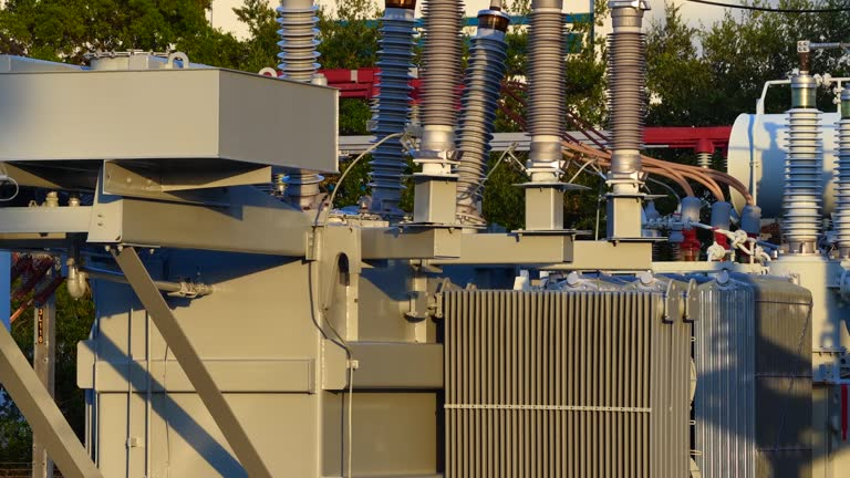

Choosing Suitable Transformer Grounding Methods for Electrical Installations
Grounding is a fundamental part of a safe and reliable electrical installation. A properly designed grounding system provides a controlled path for fault currents, helps stabilize system voltages, and supports the operation of protective devices. When transformers are incorporated into an electrical installation, selecting an appropriate grounding method is particularly important because the transformer’s winding configuration and connection to the electrical system can influence how the system responds to faults.
There is no single transformer grounding method that is appropriate for every installation. The best approach depends on factors such as system voltage, transformer configuration, fault-current requirements, protection equipment, load characteristics, and applicable electrical standards.
Understanding the available grounding methods and their applications can help engineers, contractors, and facility managers develop electrical systems that balance safety, reliability, and performance.
Understanding Transformer Grounding
Transformer grounding establishes an intentional electrical connection between an appropriate point of the transformer system and earth. Depending on the transformer configuration, grounding may be applied to a neutral point, winding connection, or other designated location.
See also: How Fire and Safety Compliance Protects People and Property
Why Transformer Grounding Is Important
A grounding system can provide a defined path for current during a ground fault. Without an appropriate grounding arrangement, fault currents may be difficult to detect or may result in undesirable voltage conditions.
Proper grounding can help:
- Stabilize phase-to-ground voltages
- Provide a path for ground-fault current
- Support protective relay operation
- Reduce the duration of certain fault conditions
- Help protect electrical equipment
- Establish a predictable system reference to ground
Grounding is therefore an important consideration when designing transformer installations.
Grounding Is Different From Bonding
Grounding and bonding are related but distinct concepts. Grounding connects an electrical system or equipment to earth, while bonding connects conductive parts together to establish electrical continuity and reduce potential differences between them.
Both functions are important in an electrical safety system and should be addressed during installation design.
Common Transformer Grounding Methods
Several grounding arrangements can be used depending on the electrical system.
Solid Grounding
With solid grounding, the transformer neutral is connected directly to the grounding system with minimal intentional impedance.
This arrangement can allow substantial ground-fault current to flow during a fault. The high current can make ground faults easier for protective equipment to detect and clear.
Solid grounding is commonly considered where rapid fault clearing is a priority and the electrical system is designed to withstand the resulting fault current.
Resistance Grounding
Resistance grounding introduces a resistor between the transformer neutral and ground.
The resistor limits the magnitude of ground-fault current to a predetermined level.
Low-Resistance Grounding
Low-resistance grounding permits a higher fault current than high-resistance grounding but still limits current compared with solid grounding.
It can provide sufficient current for protective relays to detect faults while helping limit potential damage associated with very high fault currents.
High-Resistance Grounding
High-resistance grounding significantly limits ground-fault current. In certain industrial systems, this may allow the system to continue operating temporarily following a single ground fault while an alarm alerts personnel to the condition.
The system must be designed to identify and correct the fault within the required timeframe.
Reactance Grounding
Reactance grounding uses an inductive reactance between the transformer neutral and ground to limit ground-fault current.
The amount of reactance is selected based on the desired fault-current characteristics and overall system design.
Applications of Reactance Grounding
Reactance grounding can be considered in certain medium- and high-voltage systems where engineers need to control ground-fault current while maintaining specific electrical characteristics.
Its suitability depends on system impedance, fault-current requirements, protection coordination, and transient behavior.
Grounding Transformers
Some three-phase systems do not have an accessible neutral point. In these situations, a grounding transformer can be used to establish a neutral grounding point.
Zig-Zag Grounding Transformers
A zig-zag grounding transformer is specifically designed to provide a neutral connection and a path for zero-sequence currents.
It is commonly used in systems where a neutral point is not otherwise available.
Wye-Delta Grounding Transformers
A wye-delta configuration can also provide a grounded neutral point. The configuration may be selected for specific system and protection requirements.
The appropriate grounding transformer should be selected according to system voltage, fault-current requirements, transformer ratings, and protection design.
Factors to Consider When Choosing a Grounding Method
Selecting a grounding method requires more than choosing the most commonly used option. Engineers should evaluate the complete electrical system.
System Voltage and Configuration
The system’s voltage level and transformer winding configuration strongly influence grounding requirements.
A transformer with a grounded wye secondary, for example, provides a different grounding arrangement from a delta-connected secondary.
The system designer should review the transformer nameplate, winding configuration, and electrical drawings before selecting the grounding method.
Ground-Fault Current Requirements
The desired magnitude of ground-fault current is another major consideration.
A solidly grounded system may allow relatively high fault currents, while resistance or reactance grounding can limit the current.
The selected fault-current level should support reliable protection without creating unnecessary thermal or mechanical stress on electrical equipment.
Protective Device Coordination
Grounding methods must be compatible with the protection system.
Circuit breakers, fuses, protective relays, current transformers, and other devices must be capable of detecting and clearing the expected ground-fault conditions.
Poor coordination can result in delayed fault clearing or unnecessary system interruptions.
Choosing Grounding for Different Applications
Electrical installations have different operating requirements, which can influence the appropriate grounding approach.
Industrial Facilities
Industrial plants often contain motors, generators, variable-frequency drives, control systems, and other equipment. Production continuity may be important, but personnel and equipment safety remain fundamental.
Resistance grounding may be considered in certain industrial systems where limiting ground-fault current is desirable.
Commercial Buildings
Commercial facilities typically require grounding systems that provide reliable fault protection and support safe operation of building electrical equipment.
The grounding method should be selected based on the transformer configuration, building electrical design, voltage level, and applicable codes.
Utility and Distribution Systems
Utility distribution systems can use different grounding arrangements depending on network design and operating requirements.
Grounding transformers may be used where a neutral connection needs to be established in a three-phase system.
Benefits of Proper Transformer Grounding
A suitable grounding method can provide several advantages.
Improved Electrical Safety
A controlled ground-fault path allows protective devices to respond to certain faults, reducing the duration of abnormal electrical conditions.
Better Voltage Stability
Grounding can help establish a stable reference for phase-to-ground voltages, particularly during normal and abnormal operating conditions.
Equipment Protection
Appropriately controlled fault currents can reduce the potential for excessive thermal and mechanical stress on transformers, conductors, switchgear, and other equipment.
Reliable Fault Detection
Grounding arrangements can help protective relays and circuit breakers detect ground faults and isolate affected portions of the electrical system.
Installation and Maintenance Considerations
Correct installation is essential regardless of the selected grounding method.
Grounding Conductors and Connections
Grounding conductors should be appropriately sized and securely connected. Connections should be protected from corrosion and mechanical damage.
All grounding and bonding connections should comply with the electrical design and applicable standards.
Grounding System Testing
Testing can help verify the integrity of the grounding system. Depending on the installation, tests may include continuity checks, grounding resistance measurements, insulation testing, and protective-device testing.
Testing requirements depend on the system design and relevant standards.
Periodic Inspection
Grounding connections should be inspected periodically for loose connections, corrosion, physical damage, or other problems.
Changes to the electrical system should also trigger a review of the grounding arrangement to ensure that the original design remains appropriate.
Safety and Compliance
Transformer grounding involves potentially hazardous electrical systems and should be designed and installed by qualified electrical professionals.
Follow Applicable Electrical Standards
Grounding systems should comply with relevant national and local electrical codes, industry standards, utility requirements, and manufacturer instructions.
Requirements can vary depending on voltage level, installation type, location, and system configuration.
Review the Complete Protection Scheme
Grounding should never be designed independently from the protection system. The transformer, grounding equipment, switchgear, protective relays, circuit breakers, and grounding conductors should function together as a coordinated system.
Conclusion
Choosing suitable transformer grounding methods is essential for developing safe, stable, and reliable electrical installations. Options such as solid grounding, resistance grounding, reactance grounding, and grounding transformers provide different ways to manage ground-fault current and establish an appropriate electrical reference.
The right choice depends on system voltage, transformer configuration, desired fault-current levels, protection requirements, load characteristics, and applicable electrical standards. Industrial, commercial, utility, and specialized installations may have different grounding requirements, making an individualized engineering assessment important.
Proper installation, testing, inspection, and maintenance are equally important. A well-designed grounding system can support effective fault detection, voltage stability, equipment protection, and electrical safety.
By evaluating the complete electrical system rather than selecting a grounding method in isolation, engineers and electrical professionals can develop transformer grounding arrangements that meet the operational and safety requirements of the installation.